Smart Glasses HUD
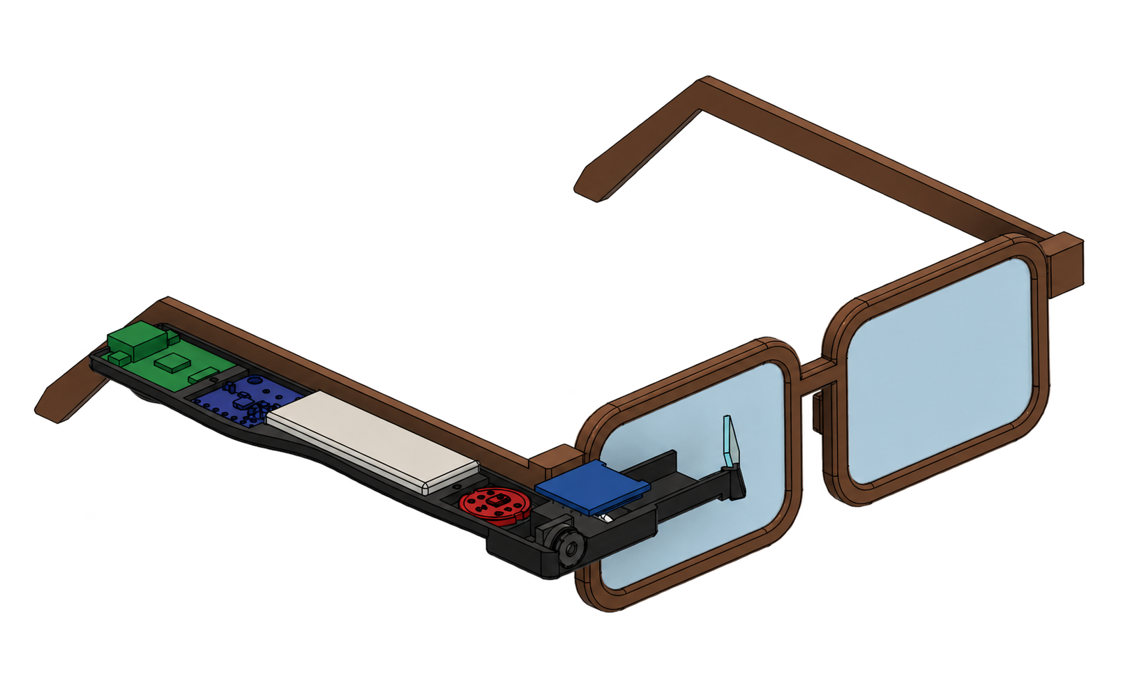
A working heads-up display developed into a V3 wearable assembly with a folded optical path, temple-mounted electronics, and an integrated enclosure.
To make useful information visible without repeatedly looking down at a phone, while keeping the optics and electronics small enough to wear.
From the initial question to a tested result
The timeline traces how the project moved through problem definition, design, prototyping, integration, and validation.
Build the adjustable optical prototype
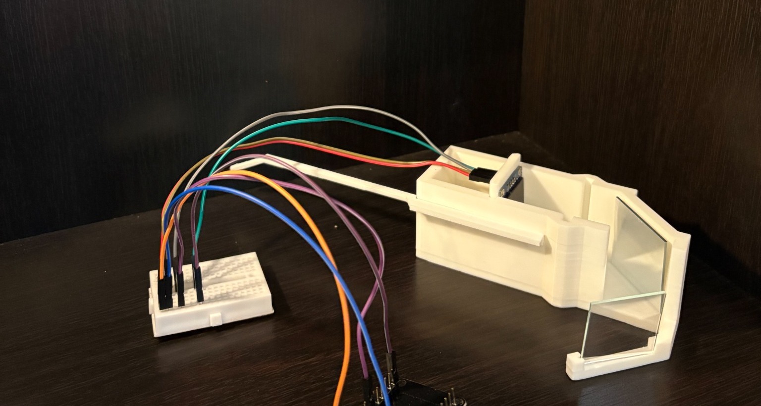
The initial physical build kept the display, controller, wiring, mirror, and combiner accessible. Optical spacing and alignment could be changed quickly before packaging the system into V3.
Verify the reflected interface
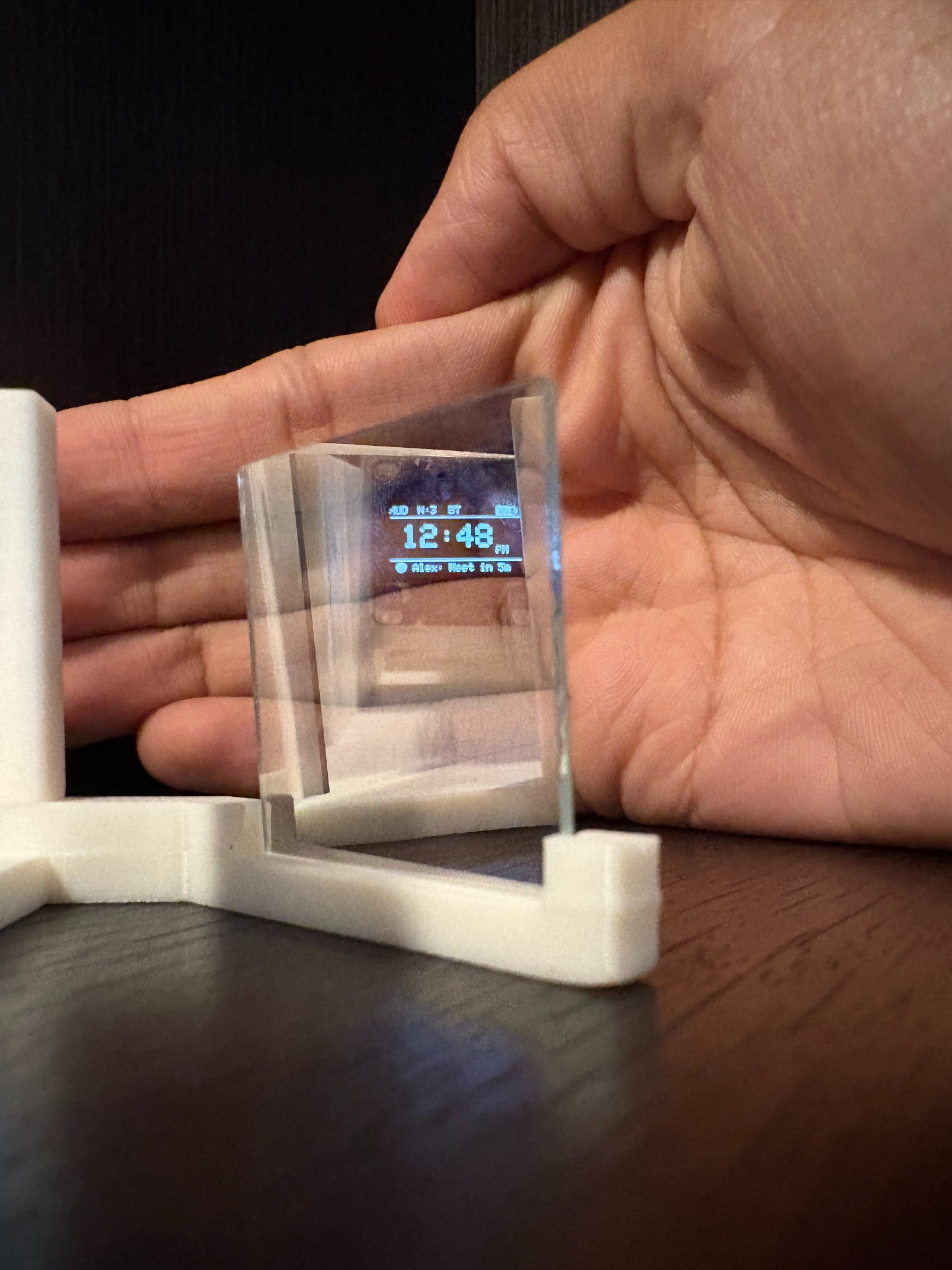
The testbed established the core path: display light reflects toward a transparent combiner, then into the eye while the surrounding scene remains visible. Keeping the mounts adjustable made image position, focus, brightness, and obstruction observable. V3 carries that same optical sequence into a compact wearable layout, replacing the exposed arrangement with a defined channel and supported optical surfaces.
Define the V3 optical geometry
Moving from the testbed to V3 meant fitting the proven reflected-image path beside the glasses temple. The display faces down onto a 45° fold mirror, turning the light 90° toward the nose through a 36 mm channel. A second fold at the combiner directs it toward the eye. The combiner sits at 45° with about 13° of downward tilt to aim the path at the pupil. The design trades the testbed’s easy adjustment for compact packaging, making mirror, channel, and eye alignment the critical geometry. The short optical path still creates a focus limitation: the roughly 67 mm optical path is too close for comfortable focus, so a roughly 50–60 mm focal-length lens is the next optical correction.
Distribute electronics along the temple
V2 was 44 mm tall. V3 lays the boards flat in a single layer along the temple, reducing the body to 8.2 mm while accepting about 21 mm of width and 125 mm of length. A face-down OLED and rotated first fold keep the display bump to 12.3 mm. Height was the priority; width and length became the space used to achieve it.
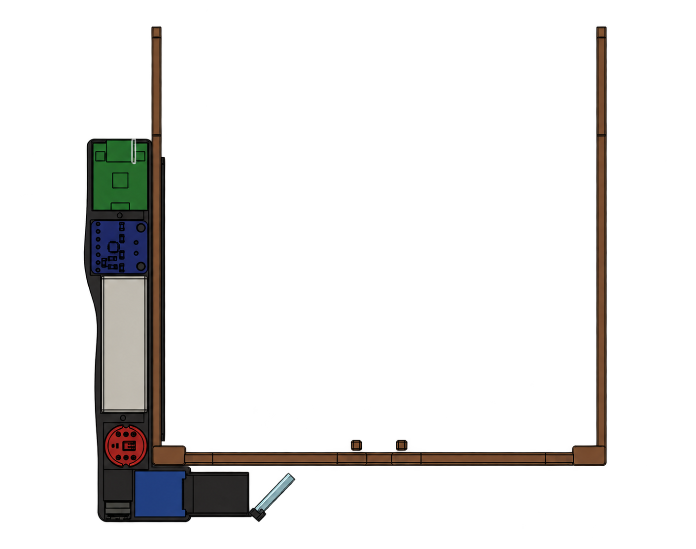
Close the enclosure around the assembly
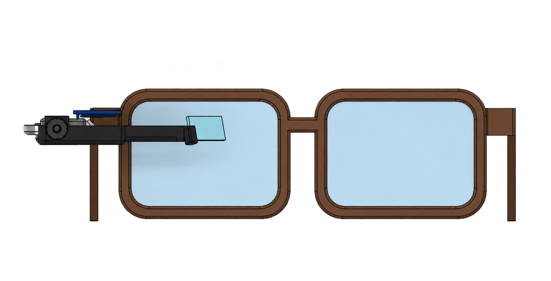
The closed V3 enclosure follows the temple and wraps around the forward optical module. Comparing the open and closed assemblies keeps internal clearance, cover access, and combiner support visible during the CAD revision.
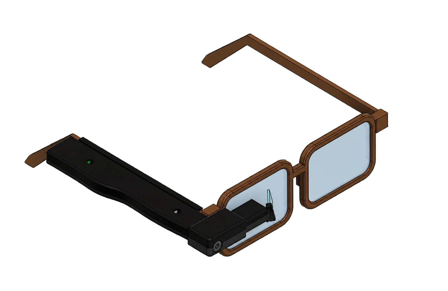
Review the complete wearable
The full assembly and interactive model bring enclosure, component packaging, glasses frame, and combiner placement into one reviewable design. I used the working prototype to establish the display concept, then developed the V3 geometry around the optical path and component clearances.
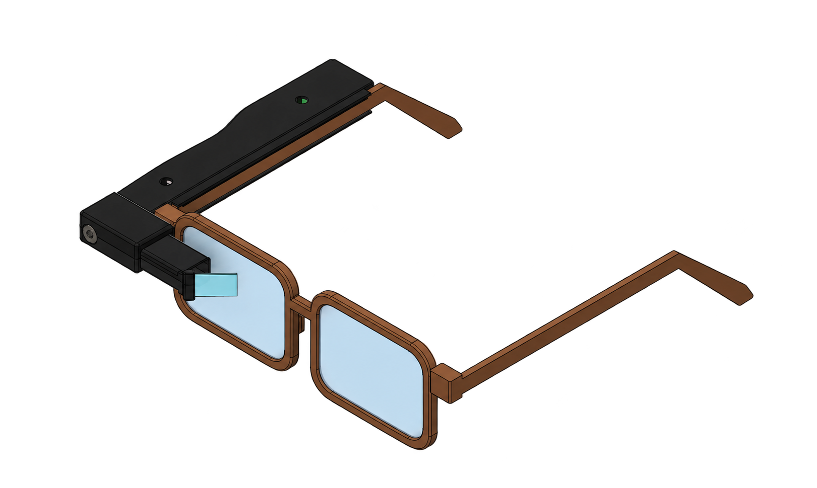
Three decisions that shaped the glasses
Fold the tested optical path into a wearable module
Keep the reflection sequence, change its orientation
I started with exposed optics so I could move the display, mirror, and combiner independently. Once I could see the interface through the combiner, the next problem was fitting that path beside a glasses arm.
A shorter package is useful only if the light still reaches the pupil. The final geometry needs tighter alignment, and the short optical distance still needs a focusing lens.
Testbed / Make alignment adjustable
I kept the optics accessible rather than designing the case first. Moving the mounts let me check where the image appeared and whether the reflected display remained visible through the combiner.
Optical test / Establish the image path
The reflected interface confirmed the basic sequence: display → mirror → combiner → eye. This gave me a physical starting point for the wearable geometry, rather than relying on CAD alone.
V3 / Rotate the first fold
I laid the OLED face down over a 45° mirror. Light turns 90° toward the nose, crosses a 36 mm channel, then reflects from the combiner toward the eye. A 13° downward tip keeps the channel at temple height while aiming at the pupil.
Final viewer / Check the geometry together
The viewer connects the screen, both reflections, and the eye position in one model. It makes alignment easier to inspect, but does not prove focus: the roughly 67 mm path still needs a lens to move the apparent image farther away.
Shrink the profile without blocking the view
Use width and length to save height
The early housing looked bulky because it was tall. I stopped treating all three dimensions equally and prioritized height, even when that meant a longer, wider package along the temple.
The body becomes about 21 mm wide and 125 mm long. Cutting the optical surfaces also reduces the margin for pupil position.
Testbed / Prove function before packaging
The exposed build gave me room to adjust optics and wiring. It was useful for testing, but its arrangement was not a wearable form factor.
V2 / Identify what sets the height
The first assembly was 44 mm tall. The full 30 × 42 mm combiner and upright components drove the profile. Shrinking the case alone would not solve that; the internal arrangement had to change.
Current V3 geometry shown for comparison; no V2 render is available.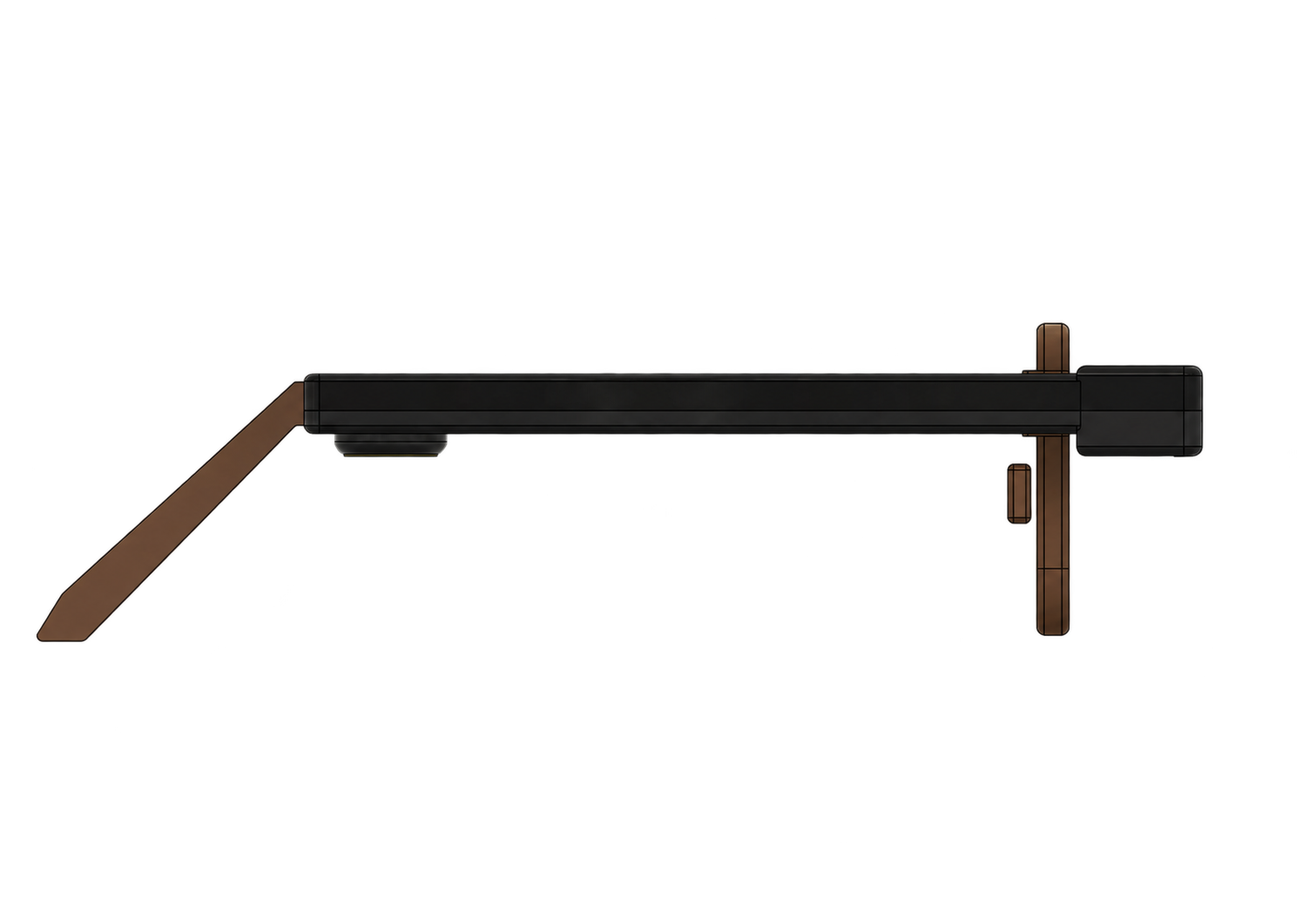
V3 / Flatten the component layer
I laid the boards and battery flat along the temple instead of stacking them. The body drops to 8.2 mm: a 6 mm arm plus 1 mm clip lips above and below. The display folds downward into a 12.3 mm bump.
V3 / Reduce the optical envelope
I reduced the combiner to 16 × 8 mm and the mirror to 8.4 × 13 mm, covering the display footprint with alignment margin. Keeping the light channel high clears the straight-ahead view; reading the HUD requires an upward glance.
Clear the straight-ahead field of view
Stop the housing short of the pupil and support the combiner at one edge
A compact HUD can still feel intrusive if its mounting hardware crosses the view. I shortened the channel so it ends 8.5 mm before the pupil line, then supported the glass with a small outer-edge clip.
The combiner has only about 1.7 mm of grip and needs adhesive. The clip must hold alignment without clipping the light.
Support only where the light does not pass
The eye-side clip jaw blocked light reaching the outer 1 mm of the combiner. I notched that jaw along the light path while keeping material above and below it. This preserves the support while opening the optical aperture.
Move the image above the main view
The tilted combiner directs the display down toward the pupil from temple height. The image sits about 18° above straight ahead, keeping the main view clear at the cost of an upward glance.