Designing a 3D-printed RC aircraft from aerodynamic analysis to flight testing
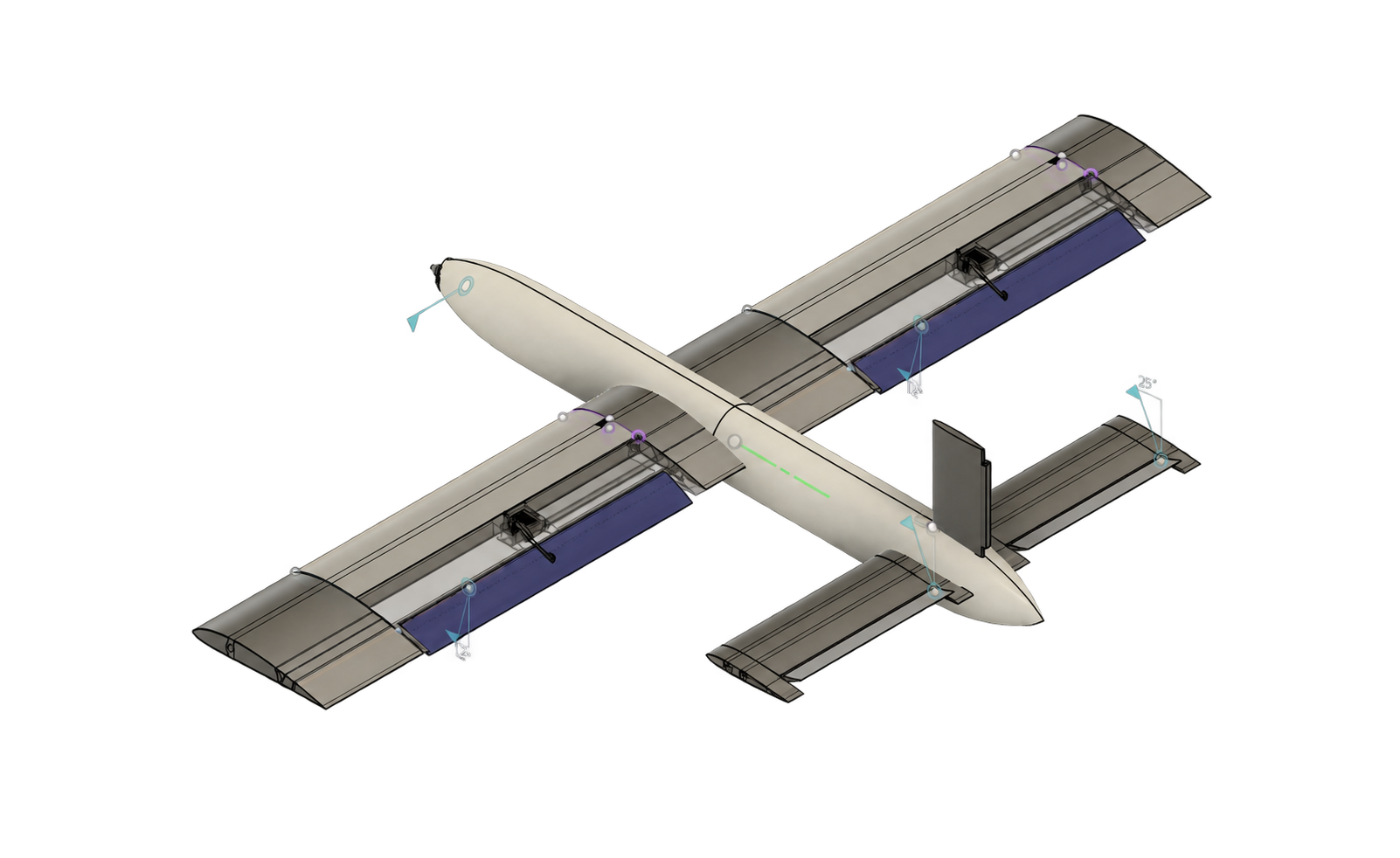
A flight-tested, modular 3D-printed aircraft developed through airfoil selection, aerodynamic modeling, lightweight CAD, and repairable assembly design.
To learn the aerospace development loop by moving from flight simulation to aerodynamic and mechanical modeling, then testing the aircraft in real flight.
From flight requirements to a tested aircraft
The project moved from defining the flight conditions to selecting an airfoil, sizing the aircraft, developing the manufacturing CAD, and validating the final design in flight.
Define the flight conditions
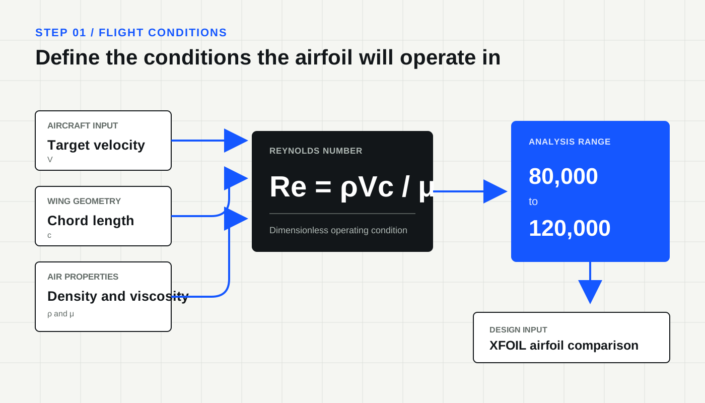
Based on the target speed and wing chord, the aircraft would operate at a Reynolds number of roughly 80,000 to 120,000. Airfoils behave differently across this low-Reynolds-number operating range, so the analysis had to reflect the conditions the aircraft would actually encounter.
Select the NACA 4412 airfoil
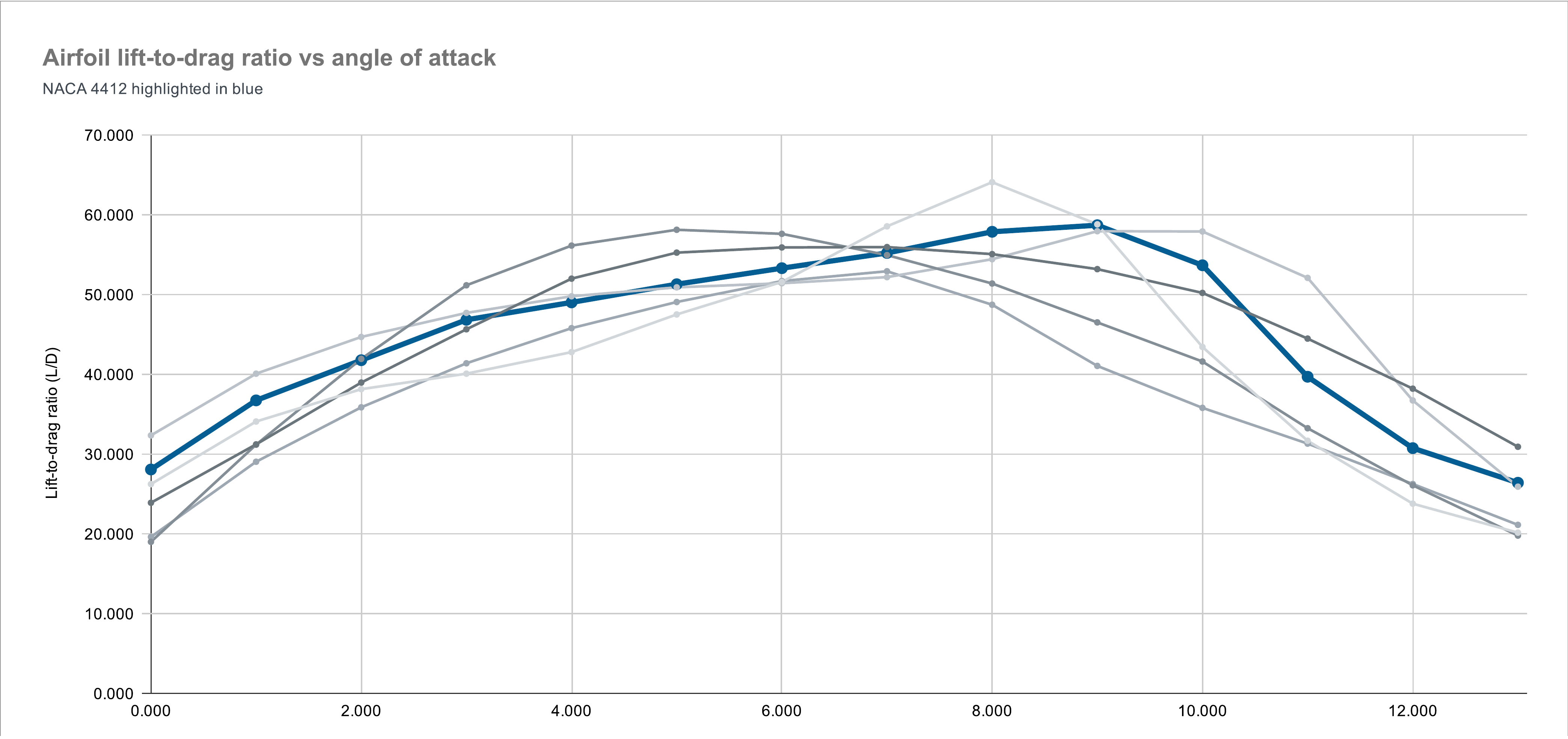
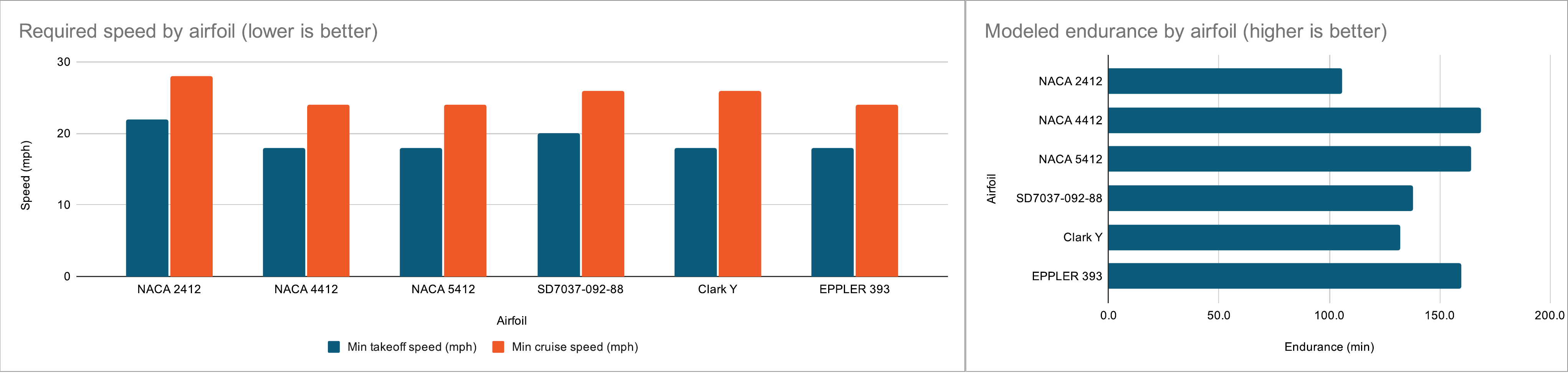
I evaluated six candidate airfoils using the same aircraft parameters. NACA 4412 tied for the lowest modeled takeoff speed at 18 mph and cruise speed at 24 mph, while also producing the longest modeled endurance at 168.7 minutes.
Evaluate the aircraft in OpenVSP
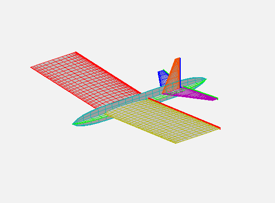
After selecting the airfoil, I built full-aircraft models with 48-inch, 42-inch, and 36-inch wingspans. The 42-inch configuration reached a peak L/D of approximately 32 near 3° to 4°, compared with approximately 22 for the 48-inch model and 19 for the 36-inch model.
Reduce wingspan from 48 to 42 inches
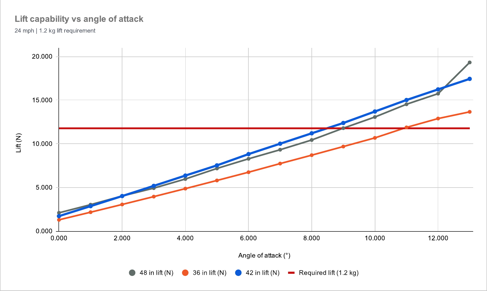
The original 48-inch configuration was too heavy, so I compared it with 42-inch and 36-inch alternatives. At 24 mph, both the 48-inch and 42-inch models crossed the 11.77 N lift requirement near 9° angle of attack. The 36-inch model did not meet the requirement until approximately 11°, leaving much less margin.
Translate aerodynamic geometry into CAD
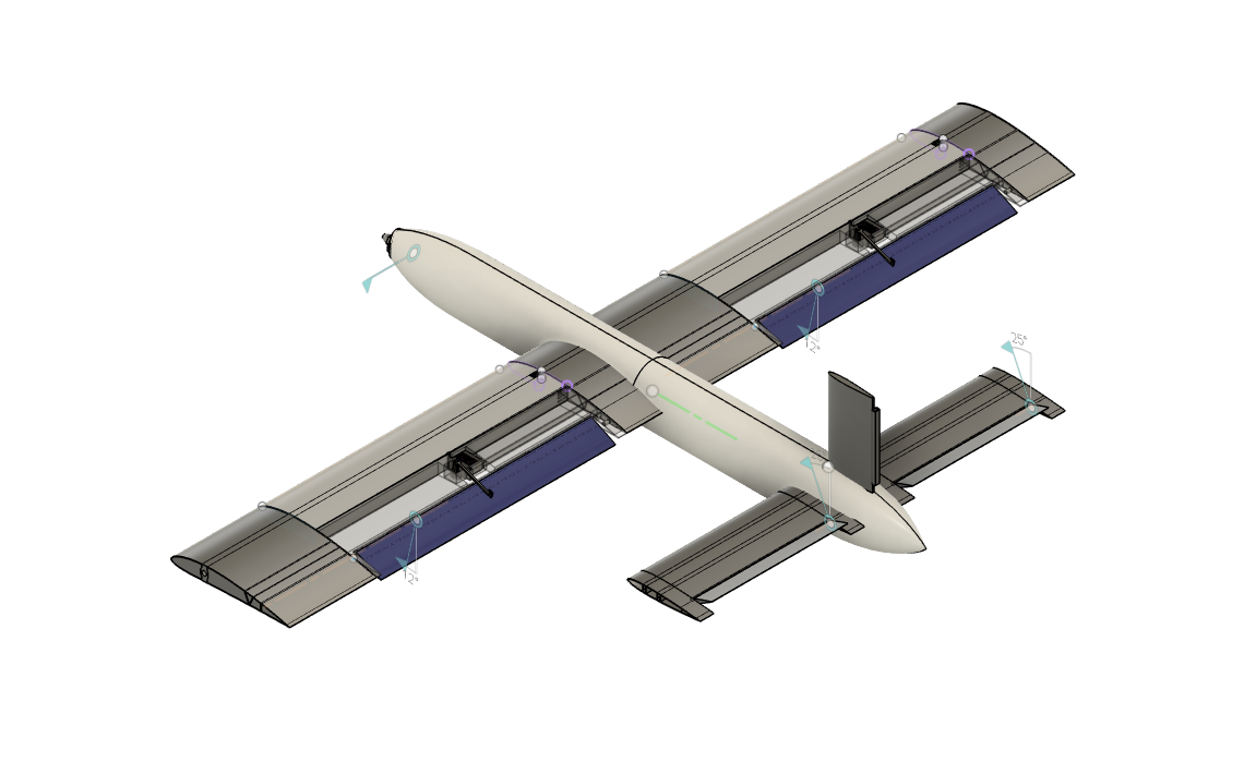
Reducing the wingspan was not enough to meet the mass target. The structure used approximately 0.8 mm PLA shells, print orientations selected around layer-direction strength, and geometry that minimized support material. Screws, heat-set inserts, and tongue joints replaced permanent adhesive connections.
Validate with flight telemetry
An onboard GPS, BMP280 barometer, and MPU6050 IMU recorded speed, altitude, acceleration, pitch, roll, and yaw. The measured takeoff speed and calculated angle of attack could then be compared with the analytical and OpenVSP targets.
Three decisions that shaped the aircraft
Each decision connects a technical constraint to the choice I made, the analysis behind it, and the tradeoff that followed.
What is the optimal airfoil for this aircraft?
NACA 4412 for balanced low-Reynolds-number performance
Under a common set of aircraft assumptions, NACA 4412 tied for the lowest modeled takeoff speed at 18 mph and cruise speed at 24 mph. It also produced the highest modeled endurance at 168.7 minutes, 4.5 minutes above NACA 5412, while maintaining a stable L/D response through the target takeoff range.
NACA 4412 did not lead every individual metric. I chose it because it performed consistently across takeoff, cruise, endurance, and L/D instead of optimizing the aircraft around one peak value.
Compare six airfoils under the same assumptions.
I evaluated six candidate airfoils using the same aircraft parameters. NACA 4412 tied for the lowest modeled takeoff speed at 18 mph and cruise speed at 24 mph, while also producing the longest modeled endurance at 168.7 minutes.
- Takeoff speed, cruise speed, endurance, and lift-to-drag ratio were considered together.
- NACA 4412 exceeded the modeled endurance of NACA 5412, the next closest candidate, by 4.5 minutes.
- The final choice favored stable performance across the intended operating range rather than one peak value.
How can we save weight without giving up takeoff performance?
Reduce the planned wingspan from 48 inches to 42 inches
The 48-inch baseline exceeded the mass target, which required a span reduction study. At 24 mph, both the 48-inch and 42-inch configurations exceeded the 11.77 N lift requirement near 9°. The 36-inch configuration required approximately 11° and provided minimal additional lift margin.
The 42-inch configuration retained less lift margin than the 48-inch baseline and saved less mass than the 36-inch concept. It was the smallest configuration that still cleared the lift requirement near the target takeoff angle.
Reduce the wingspan without giving up the takeoff margin.
The original 48-inch configuration was too heavy, so I compared it with 42-inch and 36-inch alternatives. At 24 mph, both the 48-inch and 42-inch models crossed the 11.77 N lift requirement near 9° angle of attack. The 36-inch model did not meet the requirement until approximately 11°, leaving much less margin.
- The 36-inch span offered the largest weight reduction but required a higher takeoff angle of attack.
- The 42-inch span retained nearly the same lift threshold as the 48-inch baseline while reducing structural size and mass.
- The final span was selected from the lift requirement rather than minimum size alone.
How should the airframe be designed for manufacturing and repair?
Use 0.8 mm PLA shells with mechanically fastened modular joints
The 48-inch baseline exceeded the mass target, so weight had to be reduced by scaling down the aircraft. Shell thickness, build orientation, support volume, mechanical loading, and joint design were developed concurrently during the CAD design process.
Thin shells reduced local damage tolerance, while screws and inserts added hardware mass and CAD complexity. In return, the aircraft could be printed in standard PLA and damaged modules could be replaced without cutting apart glued joints.
Design for printing, assembly, and repair.
Reducing the wingspan was not enough to meet the mass target. The structure used approximately 0.8 mm PLA shells, print orientations selected around layer-direction strength, and geometry that minimized support material. Screws, heat-set inserts, and tongue joints replaced permanent adhesive connections.
- Thin-wall shells reduced printed mass while preserving the external aerodynamic surface.
- Layer direction, local loads, support volume, and assembly access were addressed during CAD development.
- Mechanical joints added hardware mass and design complexity, but allowed individual modules to be removed, repaired, and replaced.
From OpenVSP to manufacturing CAD
OpenVSP established the system-level aerodynamic geometry and supported the wingspan trade study. The selected 42-inch configuration was then translated into a detailed Fusion 360 assembly with printable modules, control surfaces, internal structure, actuation interfaces, and removable joints.