Framing and prototyping an automated EV charging system
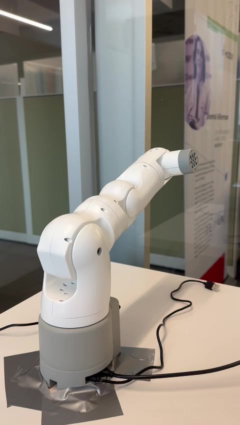
An automated EV charging concept advanced through system comparisons, rapid end-effector prototypes, and a larger integrated robotics demonstrator.
From product factors to design for manufacturing
The workflow moves from defining the problem to testing physical interfaces, selecting a direction, increasing prototype scale, and preparing the final concept for manufacturing.
Identify the product factors
The project began by mapping the factors that could determine whether an automated charging product would work in practice. These considerations became the basis for concept generation and later prototype evaluation.
- Human-robot interaction and user expectations
- Power delivery, connector handling, and cable behavior
- Vehicle access, parking variation, and physical constraints
- Safety, legal requirements, cost, controls, and buildability
Conceptualize and ideate
One concept used a physical mobile robot that could drive between vehicles and position the charging connector. It offered excellent vehicle access, but the moving platform introduced major power-delivery, safety, and human-robot interaction concerns.
- Evaluate the complete product architecture, not only the charging mechanism
- Score each concept against the same system factors
- Use critical failures to identify which risks require prototypes
- Carry the strongest elements into the next concept round
Mobile charging robot
A self-propelled platform drives to the vehicle and positions the connector at the charge port.
Rapidly prototype the riskiest interfaces
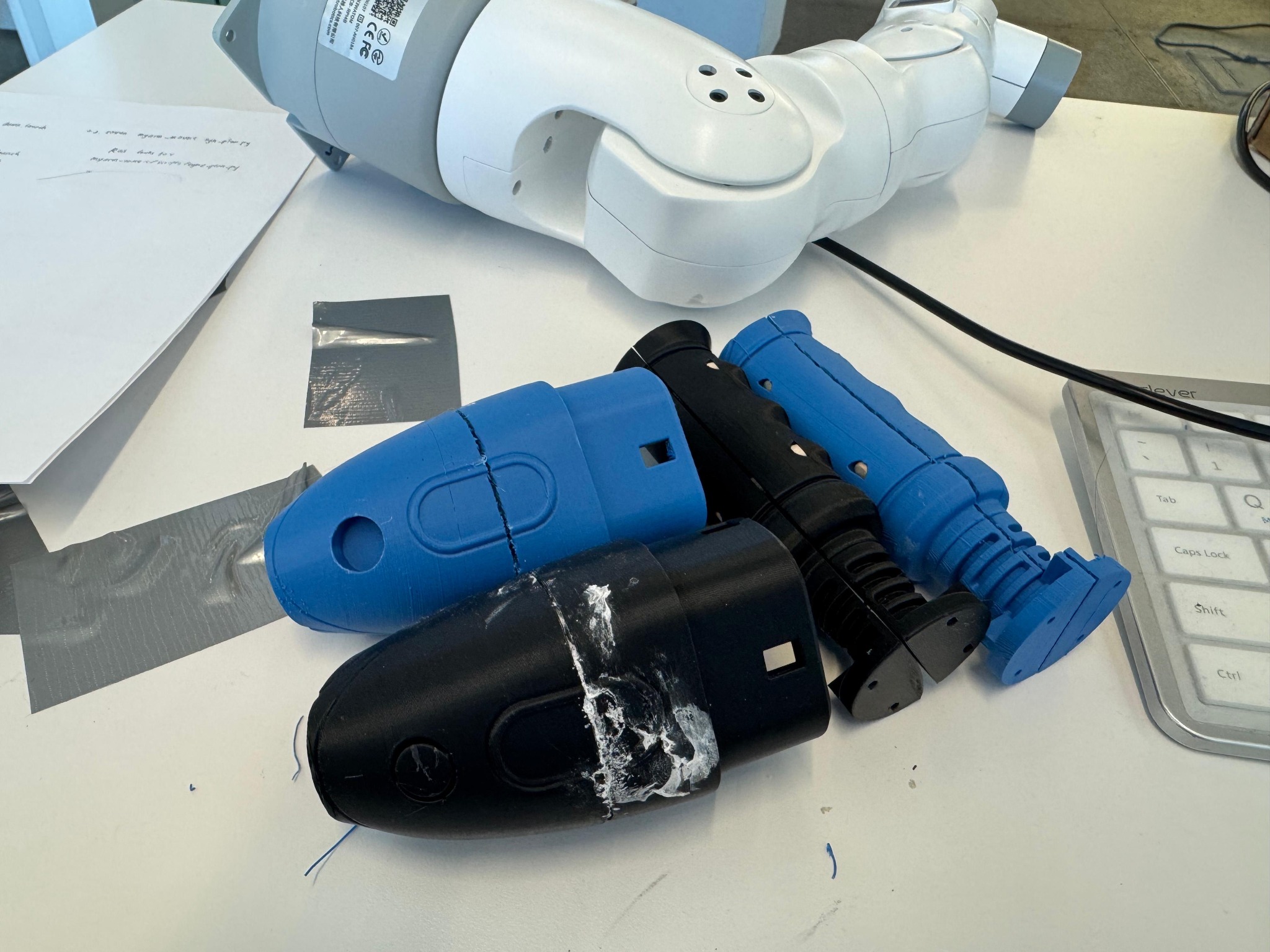
The early concepts were reduced to their highest-risk physical questions. Rapidly printed end effectors made geometry, fit, reach, connector handling, durability, and assembly issues visible before larger-scale development.
Evaluate prototypes and choose a concept
The prototypes were compared against the same product factors established at the start. Concepts advanced when they reduced the most important interface risks and remained practical to integrate into a complete system.
- Fit and usable reach
- Stability and mechanical loading
- Connector alignment and handling
- Repeatability, buildability, and integration risk
Build a larger-scale prototype
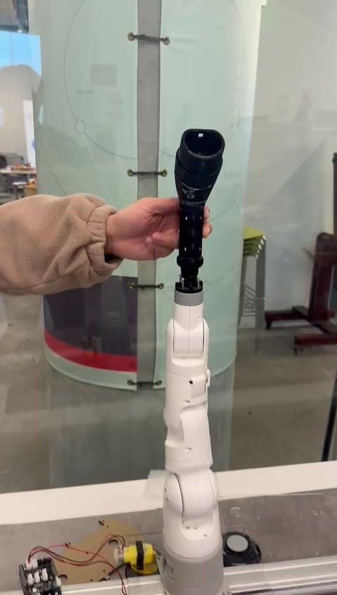
The selected direction was developed into a larger prototype so motion, packaging, controls, and subsystem coordination could be evaluated together. This stage shifted the work from isolated mechanisms toward complete system behavior.
Develop the final concept for manufacturing
The final phase focused on preparing the selected concept for design for manufacturing. CAD development considered part count, assembly sequence, material choice, tolerances, service access, cable routing, and the interfaces between mechanical and electrical subsystems.
- Reduce unnecessary part and assembly complexity
- Define tolerances and repeatable locating features
- Plan service access and cable routing
- Align materials and fabrication methods with production needs