3-DOF 3D Printed Robot Arm
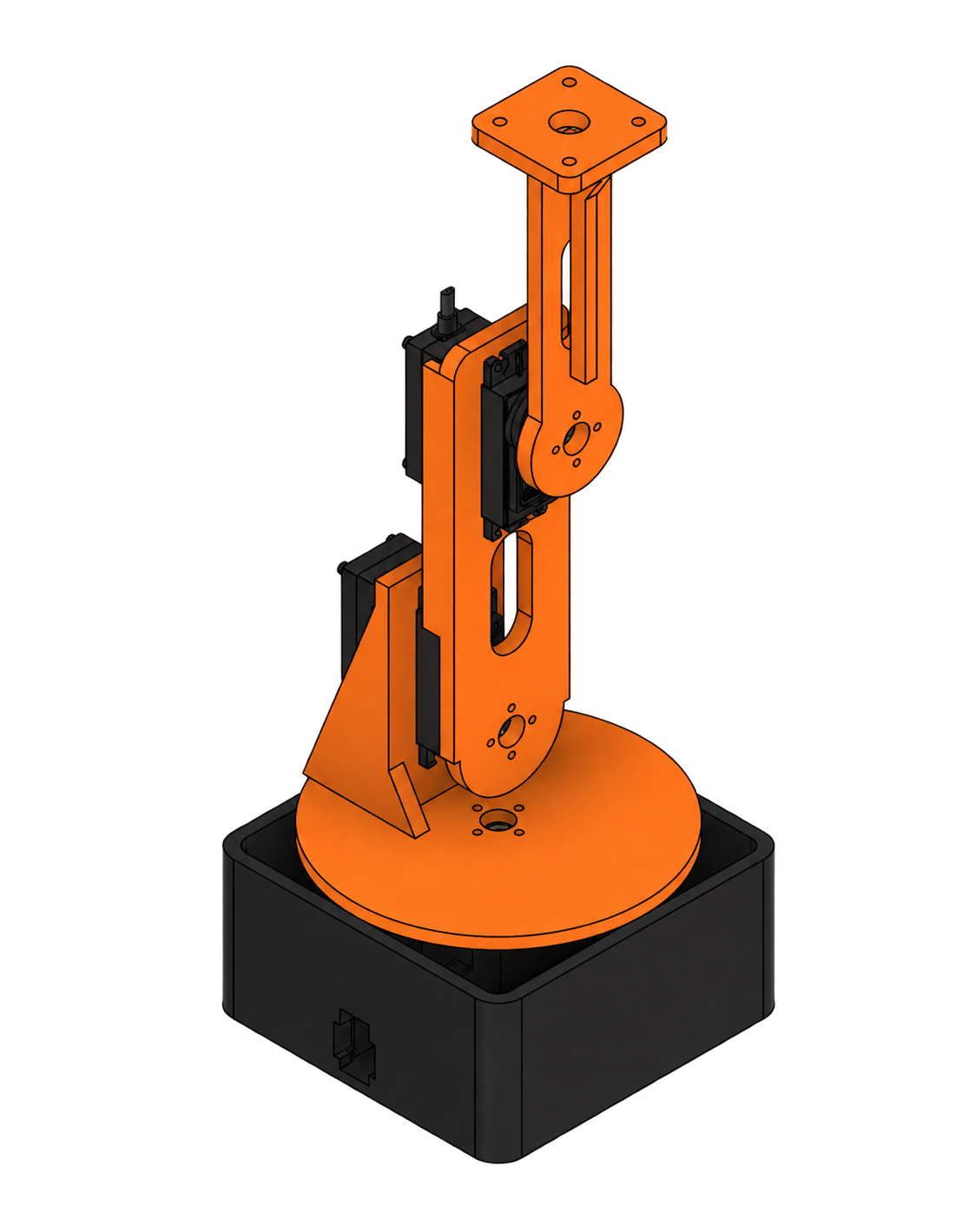
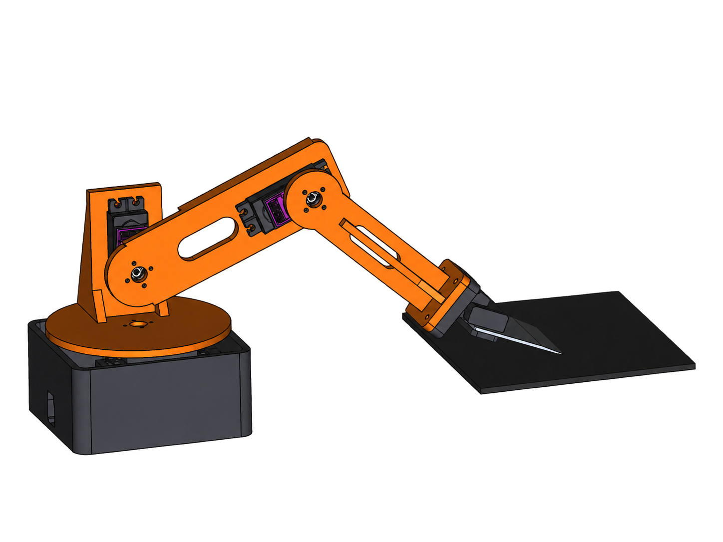
A built, servo-driven 3D printed arm for removing prints from the bed. Gripper and scraper tests informed the tool choice, while torque analysis and Python kinematics guided linkage sizing and movement.
To remove completed prints from a printer bed and connect mechanical design, robot modeling, and task-specific tooling in one system.
From torque sizing to vision-guided removal
Use a torque model
Calculate joint loads and payload margin to establish a reach and tool-mass budget.
Design the linkages
Choose the 100 mm upper link and 95 mm forearm to balance reach with shoulder torque.
Design and test end effectors
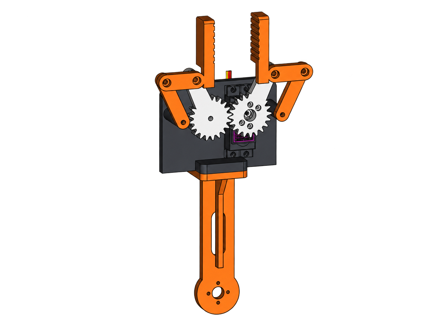
Test both tools. Select the scraper because it separates part-to-plate adhesion more effectively.
Model movement in Python
Create the Python kinematic model to meet the selected scraper’s higher positioning-accuracy requirement.
Use the model to drive the real arm
Connect modeled joint movement to the built arm and compare the predicted tool path with physical motion.
Implement computer vision
Pending: identify the print and bed, then supply a target to the movement model.
From torque limits to a print-removal tool
Enough reach. Enough lifting torque.
100 mm upper link + 95 mm forearm
Reach the print bed while leaving enough shoulder torque to lift a released print.
Longer links increase reach but reduce lifting capacity. The selected 195 mm linkage balances both.
Reach increases with length, but so does the shoulder’s load.
The tool extends beyond the links and must be included in sizing.
Reserve torque to lift the print after release.
τallow = 0.50 × 1.08 = 0.54 N·m
τremaining = 0.54 − 0.329 = 0.211 N·m
mmax = 0.211 / (9.81 × 0.299)
≈ 72 g
6 V, horizontal arm, gripper attached. The 50% limit is a design margin, not a rated continuous torque.
The reach tradeoff
| Linkage | Self-load | Payload |
|---|---|---|
| 155 mm | 0.265 N·m | 108 g |
| 195 mm | 0.329 N·m | 72 g |
| 235 mm | 0.396 N·m | 43 g |
| 275 mm | 0.465 N·m | 20 g |
Insight: 80 mm more linkage cuts modeled payload from 72 g to 20 g. Keep the selected 195 mm geometry and reduce tool mass before extending reach.
Task constraint: lifting capacity does not include bed adhesion. Release force and positioning accuracy need separate tests.
Accuracy versus strength.
Scraper selected after comparing both tools
The scraper was better able to separate part-to-plate adhesion. The gripper lacked enough strength.
The scraper required more accurate positioning and approach angle, creating the need for a kinematic model.
Gripper strength limited release.
The gripper did not have enough strength to overcome the print’s adhesion to the plate reliably.
Insight: holding the part and breaking bed adhesion are different force requirements.
The scraper separated adhesion better.
The scraper was selected after testing because it was better able to separate the print from the plate.
25.1 g tool · 159 g modeled full-reach payload
Release performance came with an accuracy requirement.
The blade needed accurate edge placement and approach angle to separate adhesion without approaching the plate incorrectly.
Design requirement: control scraper position and orientation through the arm’s joint movement.
The accuracy tradeoff drove the Python model.
I created the kinematic model to predict scraper position from the built arm’s joint angles and make its movement inspectable.
Joint angles → tool pose → controlled approach
One geometric model for movement and loading.
Python kinematics to control scraper placement
The selected scraper demanded more accurate placement. A CAD-based model connects joint angles to the tool pose needed for that approach.
Predicted movement still depends on calibrated servo commands, stiffness, and backlash in the built arm.
Base yaw, shoulder pitch, elbow pitch.
Predict scraper position from the built arm’s joint geometry.
Test geometry and torque consistency before physical control.
Insight: a consistent model makes motion inspectable. Calibration must still account for backlash, stiffness, and real servo behavior.
Built arm. Selected scraper. Kinematic model for accurate placement.
The built arm was tested with a gripper and scraper. The scraper separated part-to-plate adhesion more effectively, but demanded greater positioning accuracy. That tradeoff motivated the Python kinematic model. Computer vision remains pending.